KO6NLM
I did something fun recently: I got my amateur radio license! I've recently been interested in learning more about digital signal processing (DSP) and software-defined radio (SDR), and I thought getting licensed would be a fun way to make that concrete.
Background
My first experience with SDR was back in college. Every physics student has to take electronics lab, and part of electronics lab is using LabVIEW to do data acquisition and processing. One day, the professor did a demo for us where he used LabVIEW to build an FM radio. He connected an antenna to the computer and used LabVIEW blocks we had been using in class to sample the signal and process it down to audio that played over the speakers. I was abuzz about it the rest of the day, and the memory of that demo has stuck with me over time.
Of course, you don't need a ham radio license just to learn about signal processing concepts. But, long-term, I think I will want to try some projects that involve transmitting, and you do need a license to transmit. Besides, I think it'll be a nice way to meet some folks with similar interests. Also, I think I might just be a sucker for a test.
Getting licensed
Getting licensed is pretty straightforward if you're interested. There are three levels of amateur radio license: Technician, General, and Amateur Extra. Each license upgrade gives you additional privileges in the amateur radio bands. You need to take a multiple choice test on electronics, radio theory, and regulations. The Technician class and General class license exams are 35 questions, and the Amateur Extra class license exam is 50 questions. You must take the tests in order.
I found a test near me using the ARRL's test finder (the ARRL is the national association for amateur radio). The ARRL publishes study manuals for each test which include the entire question pool. You could simply memorize the questions and their answers, but I think it's more fun to read the books. When you're ready for practice tests, do that on HamStudy.
A note: the address you provide will be public to anyone that looks up your callsign in the FCC's database. Any mailing address you can be reached at is valid, so consider getting a P.O. Box if you want to keep your address private (that's what I did).
I took my Technician exam a couple of weeks ago and passed!
Celebrating with a project
To celebrate, I wanted to do a project that I've been putting off for a while. I live near San Francisco International Airport, and I have an RTL-SDR dongle, so let's listen to some ATC traffic.
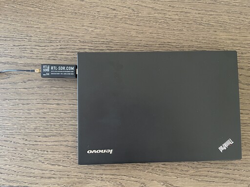
The RTL-SDR is a cheap USB TV tuner that, with the help of custom drivers, gives you programmatic access to the received radio signals, which allows it to function as a very cheap SDR. The Blog RTL-SDR v4 linked above comes with a simple dipole antenna that is effective at the VHF frequencies used by airband.
GNU Radio is an open-source package for building software radio and signal processing systems. GNU Radio gives you processing blocks for reading signals from a source, performing demodulation, outputting audio, et cetera. All the things you need to implement signal processing pipelines. GNU Radio Companion is a GUI flowgraph editor that ships with GNU Radio. GNU Radio Companion lets you quickly wire up a pipeline and generate Python code implementing it.
Setting up
I put the dipole antenna outside aligned vertically (based on my reading, airband transmissions are vertically polarized).
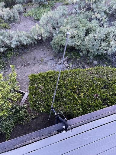
I extended each side of the dipole to about two feet which would make it most effective around the frequency of SFO's tower frequency. The signal is probably so strong that this doesn't matter a lot. Dipole antennas get the strongest reception broadside (e.g. when the tips are oriented 90 degrees from where you want to receive) so I pointed the side of the antenna toward SFO.
The antenna is connected to the RTLSDR via a coax cable and the RTLSDR is connected to the computer via USB.
We're now set up to receive data. What exactly comes out of this thing though?
Background: I/Q Data
The RTLSDR (and every software-defined radio that I know of) doesn't actually output a raw voltage signal, it outputs I/Q data. In short, it's possible to represent any modulated signal using two amplitude-modulated signals that have a 90 degree phase offset (i.e. are in quadrature phase). My understanding (which may be flawed) is that I/Q data represents the modulation signal independently from the carrier frequency. Thus, it can be sampled at a lower frequency which saves processing power. Instead of the 200 million samples per second needed to accurately reconstruct a 100MHz signal, you may only need 200 thousand samples per second to accurately reconstuct a voice signal. Additionally, later processing blocks do not need to know the carrier wave frequency.
Background: Airband modulation
In order to make sense of the data coming off the RTLSDR, we need to know the modulation details for air traffic. According to the Wikipedia article on Airband, aircraft communication is amplitude modulated with both sidebands present.
This touches on something I learned while studying for my ham radio test. AM signals have symmetric sidebands around the carrier wave. One of these sidebands can be suppressed (either the upper or lower sideband; they're functionally equivalent), and this is actually more efficient for weak signals because the full transmission power is concentrated in one sideband. I am actually not sure why airband doesn't use single-sideband!
Building the radio
We have everything we need to build our radio. I'll put the block diagram right up front and then cover the details.
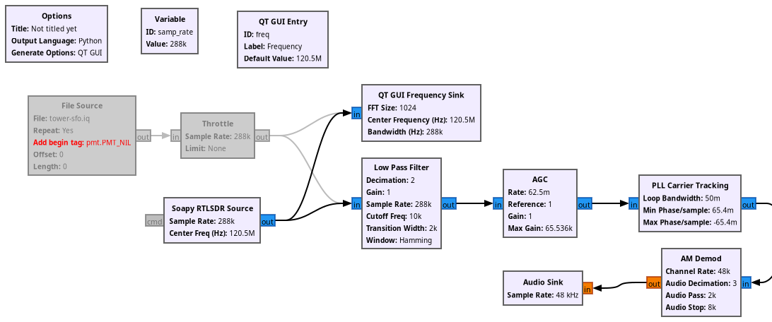
This is a minimally adapted version of the AM Demod block diagram on the GNU radio wiki.
Let's break this down a bit. In the bottom left, we see the Soapy RTLSDR source
block. That block represents the radio input to our computation graph. It
produces I/Q data in the form of complex numbers, so the out port is drawn in
blue (float outputs are drawn in orange). More on the sample rate later. The
center frequency is the frequency for SFO's tower, 120.5MHz.
Note: I also included a disabled file source and throttle. I captured the I/Q data to a file you can download if you like and follow along without your own SDR.
The output from the SDR flows into two blocks. The lower chain of blocks is the actual demodulation and I'll cover that next. The upper block is a GUI object that will draw a frequency power plot as we receive data from the radio.
As for the radio itself, we first put the signal through a low pass filter. I set this to pass frequencies less than 12kHz because the bandwidth for an airband channel is 25kHz so the maximum voice frequency that can be transmitted is 12.5kHz.
Let's talk now about the sample rate I chose earlier and how that relates to the decimation factor in this block (and in the AM demod block that comes later). When sampling I/Q data, you choose a sampling rate based on the bandwidth of the modulation signal you're trying to recover (remember, I/Q data is independent of the carrier frequeqncy: we don't have to sample at MHz just because the carrier wave is in MHz).
Additionally, there is going to be a mismatch between the input sampling frequency and the desired output sampling frequency. We bridge that gap using decimation (only keeping every Nth sample). The decimation factor must be an integer, so we want to choose a sampling frequency that is an integer multiple of 48kHz (our desired audio output frequency).
Finally, the RTLSDR only supports sampling frequencies in particular ranges. We have to select a sampling frequency that is 1) >50MHz 2) a multiple of 48kHz, and 3) in the range of supported sampling frequencies for our hardware. I chose 288kHz (48 * 6) for this application. We could decimate by a factor of 6 all at once, but I chose to decimate in two steps: first by a factor of 2 in the low-pass filter and then by a factor of 3 in the AM demodulation. I do not know if decimating in two steps is important or not: it was a random choice on my part.
Back to the flowgraph. I don't fully understand the next two blocks. AGC stands for automatic gain control and it helps regulate the volume of the output. I took the settings directly from the GNU radio wiki. I really don't understand what PLL carrier tracking is or if it's even necessary.
The next block is the actual AM demodulation block. This can be done manually using lower level blocks, but for a first experiment I'm happy to not understand this fully.
Finally after the AM demodulation we have real values instead of complex values (hence why the ports changed to orange). We can pipe the output of AM demodulation into an audio sink and finally hear some output!
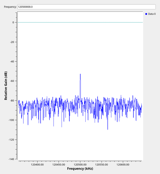
GNU radio translates this flow diagram into a Python script. We can either run this directly from GNU radio companion or we can run the Python script directly. In either case, we get a GUI with our frequency power plot and we hear some audio!
That's all for now, more later. KO6NLM clear.